

'Mini' benchmark problem with detailed equation-based modelling
| Name | Description |
|---|---|
| OpenLoop | Open loop power system |
| OpenLoopEq | Open loop power system, modelled using equations |
| PrimaryController | Primary Control System |
| PrimaryControlledSystem | System with primary controllers connected |
| ClosedLoop | Connection of OpenLoop and Primary control systems with no secondary control. |
| ClosedLoop2 | Connection of OpenLoop and Primary with secondary control. |
| NoControl | TwoNode TestCase without primary controls |
| ShedRelay | |
| SimplePrimaryController | Primary Control System |
| SimplePrimaryControlledSystem | |
| ComparePrimaryControls | |
| OpenLoopIndexReduced | |
| VerifyIdxReduced |
 ABB_CC_Testcase.TwoNode.OpenLoop

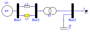
Model of the Open Loop mini test case built using the standard component library.
model OpenLoop "Open loop power system"
  Components.Slack G1(V0=1.05504739284515);
  Components.Bus Bus1;
  Components.Varimp L1;
  Components.Impedance L2(X=0.5);
  Components.Bus Bus2;
  Components.Bus Bus3;
  ABB_CC_Testcase.Components.Transformer T1(X=1e-9);
  input Integer LoadStep;
  input Integer TapStep;
  ABB_CC_Testcase.Components.FixCapacitor FixCapacitor1(B=0.2);
  Components.Load Load(P0=1, Q0=0.3);
equation
  //  L1.X = if time > 20 then Modelica.Constants.inf else 0.5;
  L1.X = if time > 10 then 1e5 else 0.5;
  Load.step = LoadStep;
  T1.tappos = TapStep;

  connect(G1.T, Bus1.T);
  connect(L2.T1, G1.T);
  connect(L1.T2, G1.T);
  connect(Bus2.T, T1.T1);
  connect(T1.T2, Bus3.T);
  connect(FixCapacitor1.T, Bus3.T);
  connect(L1.T1, Bus2.T);
  connect(L2.T2, Bus2.T);
  connect(Load.T, Bus3.T);
end OpenLoop;
 ABB_CC_Testcase.TwoNode.OpenLoopEq
Model of the Open Loop mini test case built using direct mathematical modelling.
This model is equivalent to OpenLoop.
| Name | Default | Description |
|---|---|---|
| v0 | 1.05504739284515 | |
| P0 | 1 | |
| Q0 | 0.3 | |
| B0 | 0.2 | |
| as | 0 | |
| at | 2 | |
| bs | 0 | |
| bt | 2 | |
| Tp | 60 | |
| Tq | 60 | |
| faultTime | 10 |
model OpenLoopEq "Open loop power system, modelled using equations"
  // parameters
  parameter Real v0=1.05504739284515;
  parameter Real P0=1;
  parameter Real Q0=0.3;
  parameter Real B0=0.2;
  parameter Real as=0;
  parameter Real at=2;
  parameter Real bs=0;
  parameter Real bt=2;
  parameter Real Tp=60;
  parameter Real Tq=60;
  parameter Real faultTime=10;

  output Real x[2]={xp,xq};
  output Real y[2](start={1,0}) = {v,delta};
  input Real u[3]={n,k,X};
  // variables
  Real xp;
  Real xq;
  Real v(start=1);
  Real delta;
  Real k;
  Real n;
  Real X;
equation
  // vector versions
  {der(xp),der(xq)} = {(-xp/Tp + P0*(v^as - v^at)),(-xq/Tq + Q0*(v^bs - v^bt))};

  {0,0} = {v*sin(delta)*v0/(X*n) + (1 - k)*(xp/Tp + P0*v^at),-(v0*v*cos(delta))
    /(n*X) + v^2/(n^2*X) - B0*v^2 + (1 - k)*(xq/Tq + Q0*v^bt)};
initial equation
  der(xp) = 0;
  der(xq) = 0;
end OpenLoopEq;
 ABB_CC_Testcase.TwoNode.PrimaryController
This model models the primary control systems of the
four node power system.
It contains a tap changer controller for transformer T1
modelled as a state machine and an automatic voltage regulator
with filed voltage limiter modelled by a state machina and a linear
control law.
The special equations activated by the flag SimulinkSafe
flag are jus fixes that must be applied to make the model simulable with
Simulink. If you remodel this system with other tools,
use the original equations (assume that SimulinkSafe=false)
| Name | Default | Description |
|---|---|---|
| idle0 | false | |
| wait0 | true | |
| action0 | false | |
| tappos0 | 0 | |
| timer0 | 0 | |
| up_limit0 | false | |
| TapDelay | 30 | |
| MechDelay | 1 | |
| TapDB | 0.01*3 | |
| MaxTap | 10 | |
| MinTap | -10 |
model PrimaryController "Primary Control System"
  parameter Boolean idle0=false;
  parameter Boolean wait0=true;
  parameter Boolean action0=false;
  parameter Integer tappos0=0;
  parameter Real timer0=0;
  parameter Boolean up_limit0=false;

  input Real TapVref(start=1);
  input Real v(start=1);

  Boolean idle(start=idle0, fixed=true);
  Boolean wait(start=wait0, fixed=true);
  Boolean action(start=action0, fixed=true);
  Integer tappos(start=tappos0, fixed=true);
  Real timer(start=timer0, fixed=true);

  Boolean toohigh;
  Boolean toolow;

  output Integer T1tappos;

  parameter Real TapDelay=30;
  parameter Real MechDelay=1;
  parameter Real TapDB=0.01*3;
  parameter Real MaxTap=10;
  parameter Real MinTap=-10;

equation
  T1tappos = pre(tappos);
  // tap changer control - state automata !
  toohigh = (v - TapVref) > TapDB/2;
  toolow = (v - TapVref) < -TapDB/2;

  idle = (pre(idle) or pre(wait)) and not (toohigh or toolow) or (pre(action)
     and ((time - timer) > TapDelay + MechDelay));
  wait = (pre(idle) and (toohigh or toolow)) or pre(wait) and ((toolow or
    toohigh) and ((time - pre(timer)) < TapDelay));
  action = (pre(wait) and (time - timer > TapDelay)) or pre(action) and ((time
     - timer) < TapDelay + MechDelay);
  when wait and not pre(wait) and not initial() then
    timer = time;
  end when;
  when pre(action) and not action then
    if toolow and (pre(tappos) < MaxTap) then
      tappos = pre(tappos) + 1;
    elseif toohigh and (pre(T1tappos) > MinTap) then
      tappos = pre(tappos) - 1;
    else
      tappos = pre(tappos);
    end if;
  end when;
end PrimaryController;

Connection of OpenLoop and Primary control systems
| Name | Default | Description |
|---|---|---|
| faultTime | 10 | |
| tapstepsize | 0.02 | |
| loadstepsize | 0.05 |
model PrimaryControlledSystem
  "System with primary controllers connected"
  ABB_CC_Testcase.TwoNode.OpenLoopEq System;
  ABB_CC_Testcase.TwoNode.PrimaryController PrimCon;
  parameter Real faultTime=10;
  parameter Real tapstepsize=0.02;
  parameter Real loadstepsize=0.05;

  input Real LoadStep;
equation
  System.u = {1 + tapstepsize*PrimCon.T1tappos,LoadStep*loadstepsize,if time >
    faultTime then 0.5 else 0.25};
  PrimCon.v = System.v;
  PrimCon.TapVref = 1;
end PrimaryControlledSystem;
Connection of OpenLoop and Primary control systems with no secondary control.
model ClosedLoop
  "Connection of OpenLoop and Primary control systems with no secondary control."


  ABB_CC_Testcase.TwoNode.PrimaryControlledSystem System(faultTime=90);
equation
  System.LoadStep = 0;
end ClosedLoop;

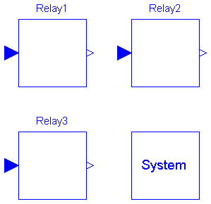
Connection of OpenLoop and Primary control systems with secondary control using
undervoltage load shedding relays.
model ClosedLoop2
  "Connection of OpenLoop and Primary  with  secondary control."
  ShedRelay Relay1(
    Threshold=.8,
    DelayTime=1.5,
    ShedAmount=.05);
  ShedRelay Relay2(
    Threshold=.82,
    DelayTime=3,
    ShedAmount=.05);
  ShedRelay Relay3(
    DelayTime=6,
    ShedAmount=0.05,
    Threshold=.92);
equation
  Relay1.inPort.signal[1] = System.System.v;
  Relay2.inPort.signal[1] = System.System.v;
  Relay3.inPort.signal[1] = System.System.v;
  System.System.k = Relay1.y + Relay2.y + Relay3.y;
public
  ABB_CC_Testcase.TwoNode.PrimaryControlledSystem System;
end ClosedLoop2;

This is a model of the twonode testcase, where no primary control systems has been connected.
Instead the tap ratio is fixed at 1 p.u. and the load shedding input at 0 p.u.
A fault on the the line is modelled of the change of the line impedance from 0.25 to 0.5 p.u. at
time 10 s.
| Name | Default | Description |
|---|---|---|
| faultTime | 30 |
model NoControl "TwoNode TestCase without primary controls"
  parameter Real faultTime=30;
  ABB_CC_Testcase.TwoNode.OpenLoopEq System;
equation
  System.u = {1,0,if time > faultTime then 0.5 else 0.25};
end NoControl;
 ABB_CC_Testcase.TwoNode.ShedRelay
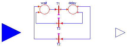
Standard load shedding relay.
| Name | Default | Description |
|---|---|---|
| Threshold | 0.95 | |
| DelayTime | 1 | |
| ShedAmount | 0.05 |
class ShedRelay
  extends Modelica.Blocks.Interfaces.SISO;
  parameter Real Threshold=0.95;
  parameter Real DelayTime=1;

  parameter Real ShedAmount=0.05;
  discrete Real timerstart(start=-1, fixed=true);

  ModelicaAdditions.PetriNets.Transition T1;
  ModelicaAdditions.PetriNets.Transition T2;
  ModelicaAdditions.PetriNets.Place12 delay;
  ModelicaAdditions.PetriNets.Transition T3;
  ModelicaAdditions.PetriNets.Place21 wait(initialState=true);
equation
  connect(delay.inTransition, T1.outTransition);
  connect(T3.inTransition, delay.outTransition1);
  connect(delay.outTransition2, T2.inTransition);
  connect(T1.inTransition, wait.outTransition);
  connect(T2.outTransition, wait.inTransition2);
  connect(T3.outTransition, wait.inTransition1);

  T1.condition = (u < Threshold) and (y < ShedAmount/10);
  T2.condition = (u > Threshold);
  T3.condition = time > timerstart + DelayTime;

  when delay.state then
    timerstart = time;
  end when;

  when T3.condition and delay.state then
    outPort.signal[1] = ShedAmount;
  end when;
initial equation
  wait.state = true;
  delay.state = false;
  y = 0;
end ShedRelay;
 ABB_CC_Testcase.TwoNode.SimplePrimaryController
This model models the primary control systems of the
four node power system using a simplified discrete-time approximation.
| Name | Default | Description |
|---|---|---|
| tappos0 | 0 | |
| up_limit0 | false | |
| TapDelay | 30 | |
| MechDelay | 1 | |
| TapDB | 0.01*3 | |
| MaxTap | 10 | |
| MinTap | -10 |
model SimplePrimaryController "Primary Control System"
  parameter Integer tappos0=0;
  parameter Boolean up_limit0=false;

  input Real TapVref(start=1);
  input Real v(start=1);

  Integer tappos(start=tappos0, fixed=true);

  Boolean toohigh;
  Boolean toolow;

  output Integer T1tappos;

  parameter Real TapDelay=30;
  parameter Real MechDelay=1;
  parameter Real TapDB=0.01*3;
  parameter Real MaxTap=10;
  parameter Real MinTap=-10;

equation
  when sample(0, TapDelay + MechDelay) then
    // tap changer control - simple discrete implementation
    toohigh = (v - TapVref) > TapDB/2;
    toolow = (v - TapVref) < -TapDB/2;
    if toolow and (pre(tappos) < MaxTap) then
      tappos = pre(tappos) + 1;
    elseif toohigh and (pre(T1tappos) > MinTap) then
      tappos = pre(tappos) - 1;
    else
      tappos = pre(tappos);
    end if;
  end when;
  T1tappos = pre(tappos);
end SimplePrimaryController;

| Name | Default | Description |
|---|---|---|
| faultTime | 10 | |
| tapstepsize | 0.02 | |
| loadstepsize | 0.05 |
model SimplePrimaryControlledSystem
  ABB_CC_Testcase.TwoNode.OpenLoopEq System;
  ABB_CC_Testcase.TwoNode.SimplePrimaryController PrimCon;
  parameter Real faultTime=10;
  parameter Real tapstepsize=0.02;
  parameter Real loadstepsize=0.05;

  input Real LoadStep;
equation
  System.u = {1 + tapstepsize*PrimCon.T1tappos,LoadStep*loadstepsize,if time >
    faultTime then 0.5 else 0.25};
  PrimCon.v = System.v;
  PrimCon.TapVref = 1;
end SimplePrimaryControlledSystem;
model ComparePrimaryControls
  ABB_CC_Testcase.TwoNode.SimplePrimaryControlledSystem SimpleSystem;
  ABB_CC_Testcase.TwoNode.PrimaryControlledSystem System;
equation
  System.LoadStep = 0;
  SimpleSystem.LoadStep = 0;
end ComparePrimaryControls;
 ABB_CC_Testcase.TwoNode.OpenLoopIndexReduced
Model of the Open Loop mini test case built using direct mathematical modelling.
This model is equivalent to OpenLoop.
| Name | Default | Description |
|---|---|---|
| v0 | 1.05504739284515 | |
| P0 | 1 | |
| Q0 | 0.3 | |
| B0 | 0.2 | |
| as | 0 | |
| at | 2 | |
| bs | 0 | |
| bt | 2 | |
| Tp | 60 | |
| Tq | 60 | |
| faultTime | 10 |
model OpenLoopIndexReduced
  // parameters
  parameter Real v0=1.05504739284515;
  parameter Real P0=1;
  parameter Real Q0=0.3;
  parameter Real B0=0.2;
  parameter Real as=0;
  parameter Real at=2;
  parameter Real bs=0;
  parameter Real bt=2;
  parameter Real Tp=60;
  parameter Real Tq=60;
  parameter Real faultTime=10;

  output Real x[2]={xp,xq};
  output Real y[2](start={1,0}) = {v,delta};
  input Real u[3]={n,k,X};

  Real[2, 2] gx;
  Real[2, 2] gy;
  Real[2, 1] f;
  Real[2, 1] g;
  Real[2, 2] invgy;

  // variables
  Real xp;
  Real xq;
  Real v(start=1);
  Real delta;
  Real k;
  Real n;
  Real X;
equation
  // vector versions
  f = [-xp/Tp + P0*(v^as - v^at); -xq/Tq + Q0*(v^bs - v^bt)];
  [der(xp); der(xq)] = f;
  g = [v*sin(delta)*v0/(X*n) + (1 - k)*(xp/Tp + P0*v^at); -(v0*v*cos(delta))/(n
    *X) + v^2/(n^2*X) - B0*v^2 + (1 - k)*(xq/Tq + Q0*v^bt)];

  gx = [(1 - k)/Tp, 0; 0, (1 - k)/Tq];
  gy = [sin(delta)*v0/X/n + (1 - k)*P0*v^at*at/v, v0*v*cos(delta)/X/n; -v0*cos(
    delta)/X/n + 2*v/n^2/X - 2*B0*v + (1 - k)*Q0*v^bt*bt/v, v*sin(delta)*v0/X/n];

  invgy = [v*sin(delta)*X*n^2/(sin(delta)^2*n*v0*v - sin(delta)*n^2*P0*v^at*at*
    X*k + sin(delta)*n^2*P0*v^at*at*X + v0*cos(delta)^2*n*v - 2*cos(delta)*v^2
     + 2*cos(delta)*B0*v^2*X*n^2 + cos(delta)*Q0*v^bt*bt*X*n^2*k - cos(delta)*
    Q0*v^bt*bt*X*n^2), -v*cos(delta)*X*n^2/(sin(delta)^2*n*v0*v - sin(delta)*n^
    2*P0*v^at*at*X*k + sin(delta)*n^2*P0*v^at*at*X + v0*cos(delta)^2*n*v - 2*
    cos(delta)*v^2 + 2*cos(delta)*B0*v^2*X*n^2 + cos(delta)*Q0*v^bt*bt*X*n^2*k
     - cos(delta)*Q0*v^bt*bt*X*n^2); (v0*cos(delta)*n*v - 2*v^2 + 2*B0*v^2*X*n^
    2 + Q0*v^bt*bt*X*n^2*k - Q0*v^bt*bt*X*n^2)*X*n/v/v0/(sin(delta)^2*n*v0*v -
    sin(delta)*n^2*P0*v^at*at*X*k + sin(delta)*n^2*P0*v^at*at*X + v0*cos(delta)
    ^2*n*v - 2*cos(delta)*v^2 + 2*cos(delta)*B0*v^2*X*n^2 + cos(delta)*Q0*v^bt*
    bt*X*n^2*k - cos(delta)*Q0*v^bt*bt*X*n^2), -(-sin(delta)*v0*v + P0*v^at*at*
    X*n*k - P0*v^at*at*X*n)*X*n^2/v/v0/(sin(delta)^2*n*v0*v - sin(delta)*n^2*P0
    *v^at*at*X*k + sin(delta)*n^2*P0*v^at*at*X + v0*cos(delta)^2*n*v - 2*cos(
    delta)*v^2 + 2*cos(delta)*B0*v^2*X*n^2 + cos(delta)*Q0*v^bt*bt*X*n^2*k -
    cos(delta)*Q0*v^bt*bt*X*n^2)];

  //   [0; 0] = g;
  //  [der(v); der(delta)] = -invgy*gx*f;
  [0; 0] = gx*f + gy*[der(v); der(delta)];
initial equation
  gx*f = [0; 0];
  g = [0; 0];

end OpenLoopIndexReduced;

model VerifyIdxReduced
  OpenLoopIndexReduced OpenLoopIndexReduced1;
equation
  OpenLoopIndexReduced1.u = {1,0,if time > 10 then 0.5 else 0.25};
end VerifyIdxReduced;